
Total 64 programs can be saved into the non-volatile memory, and each program contains up to 30 test steps.
#Return loss bridge rlb 251 series#
The Multi-Step mode is capable of running a series of measurements of a component at a number of user-defined steps in sequence automatically. Either Pass or Fail result can be set with a buzzer alarm, which makes component or material sorting easy with sound identification. This scale and bar also facilitate the adjustment of the variable components. A scale and bar for displaying measurement result is shown at the center of the screen to give a graphical identification, which greatly reduces operator's load in a long time inspection work. The Pass/Fail test checks whether the parameter measurement result sits within the limits, then display "PASS" for within the limits, or "LO" for lower than the low limit, or "HI" for higher than the high limit. Three methods, including absolute limit, percentage and delta limit, are available for Hi(high) and Lo(low) limit setting based on the nominal test value. In the Pass/Fail test, primary parameter measurement result is compared with user-defined limits and the pass or fail result is then displayed. The large LCD display with single-layer operation menu of LCR-8000GSeries provides users with ultimate convenience to plug and play without much learning time. The LCR-8000G Series is designed to perform precision impedance measurements over a wide frequency range of 20Hz~10MHz for LCR-8110G, 20Hz~5MHz for LCR-8105G and 20Hz~1MHz for LCR-8101G.The instrument is capable of measuring 11 different parameters with0.1% basic accuracy, which meets the precision measurement requirements of components and modules used in the RF circuits. The rich features of LCR-8000G Series easily make your measurement tasks done at a very competitive price. GPIB and RS-232C interfaces are available as standard for instrument control and test result display on the PC. This gives an analysis result of either impedance vs. With Graph Mode, LCR-8110G, LCR-8105G and LCR-8101G display the component impedance response either over a wide range of test frequency sweep or over a wide range of test voltage sweep in a graph chart. Under Multi-Step operation, a tedious work routine can be done step by step automatically just at a press of a button. Each program includes 30 test steps and each test step can be set with selected parameters and test limits. The Multi-Step function allows on-screen programming of customized measurement sequence with Pass/Fail indication. The LCR-8000G Series LCR meter, with test frequency up to 10MHz, provides accuracy, versatility and high resolution for a wide range of component measurements, even including DC resistance measurement and Voltage/Current monitoring. (*)‟Basic accuracy varies with the speed, frequency, AC signal level and impedance of the device under test. Impedance (Z), Phase Angle (ƒÆ), Inductance (L), Capacitance (C), AC Resistance (Rac), Quality Factor (Q), Dissipation Factor (D), Admittance (Y), Conductance (G), Reactance (X), Susceptance (B), DC Resistance (Rdc)ĪC 115V(+10% / -25%), 230V(+15% / -14%) (Selectable), 50/60Hz Each housing is blue baked enamel per Federal Standard 595 #25109 over primer wash per DOD-P-15328.20Hz ~ 10 / 5 / 1 MHz, 5 Digits, }0.005% This high sensitivity allows for measuring equivalent SWR of 1:101 or better.Įach RLB-I Return Loss Bridge comes completely assembled in a premium shielded die cast aluminum alloy A380 housing. Most bridges have a residual return loss from 30-40 dB (1000-1 to about 10,000). If the impedances of the internal reference to the DUT are exactly equal, than the detector output will be essential zero (0). The DUT (device under test) is connected to the item to be tested such as an antenna, network, coax, or any other device.


The DET (detector) is connected to an oscilloscope or spectrum analyzer for analysis.
#Return loss bridge rlb 251 generator#
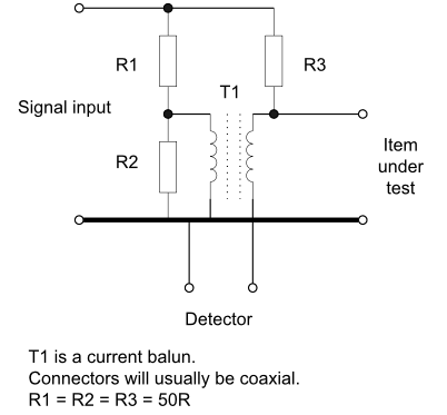
The INPUT port is connected to a test frequency source such as an RF oscillator or tracking generator from a spectrum analyzer. Return Loss Bridges operate by comparing the unknown impedance to a reference impedance.

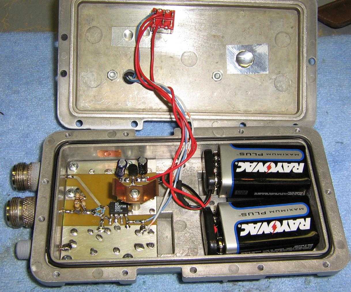
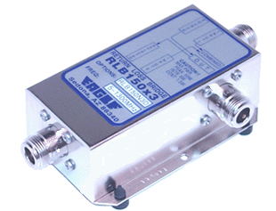
The bridge components are precision SMD devices with a wide band 1:1 750 MHz SMD transformer using micro strip construction. The internal reference impedance is 50 ohms. The RLB-I internal reference (three ports) is a high performance ReturnLoss Bridgeoptimized for ham radio applications.


 0 kommentar(er)
